Revolved Section View

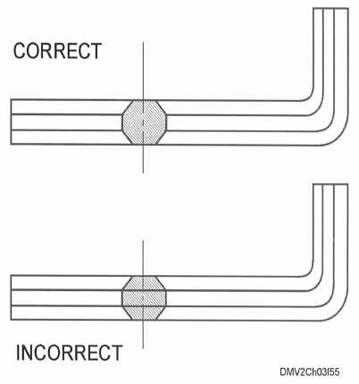
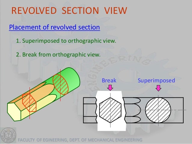
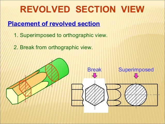
Revolved sections a revolved section shows the shape of an object by rotating a section 90 degrees to face the viewer.
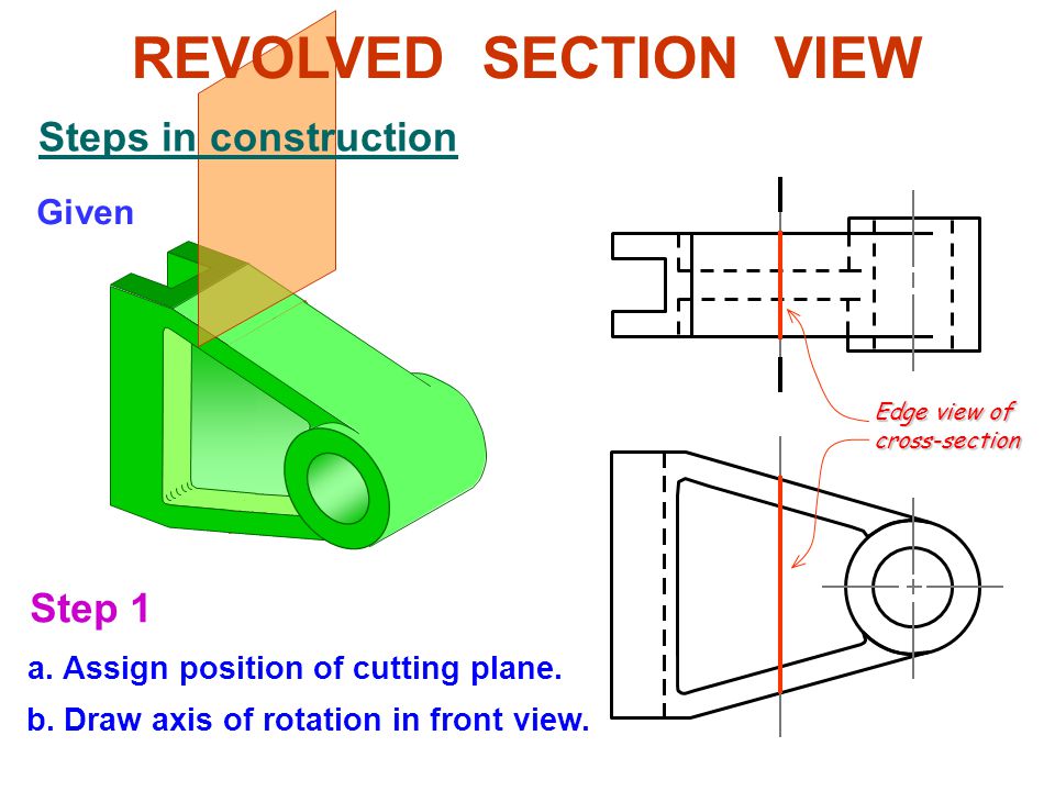
Revolved section view. In a drawing select a view. Revolved section view basic concept steps in construction. Revolved section when a drawing has may numbers of long structural members of different cross sections it is very difficult to identify the cross section of the member.
Views continued revolved sections revolved sections are cross sections of an elongated form or object rotated toward the plane of projection to show its shape or contour. A full section view is where the entire part or assembly is cut on a single plane. A partial section is.
The three revolved sections illustrated in the spear like object of figure 12 show the changes that take place in its shape. Revolved sections are made by assuming a plane perpendicular to the centerline or axis of the bar or other object and then revolving the plane through 90 degrees about a centerline at right angles to the axis. The edges must be.
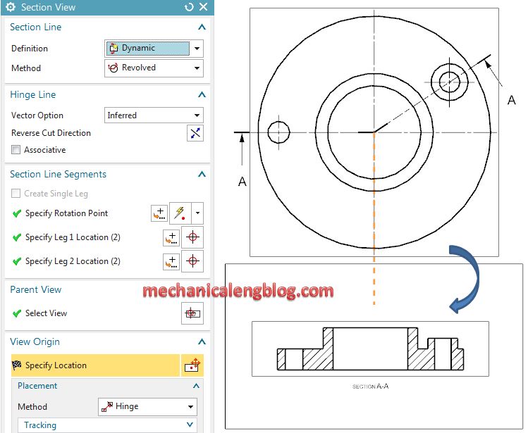
According to ansi the type of section lining used for all materials should generally be the same as that for. Removes a small amount of material to show the interior details. In the graphics window we will select the rotation point for a revolved.
License creative commons attribution license reuse allowed show more show less. Drop a cutting plane perpendicular to the axis of the object and revolve the plane 90 degrees around a centerline and at a right angle to the axis. Used to enhance the orthographic view by giving the viewer a better look at key interior details.
Retain the true shape of the revolved section regardless of the direction of the lines in the view. Click removed section view layout commandmanager tab or drawing toolbar. Object may be shown by means of a revolved section.
